Quickstart: an angle bracket
Don't have BearCAD yet? Run it in your browser or download it here.
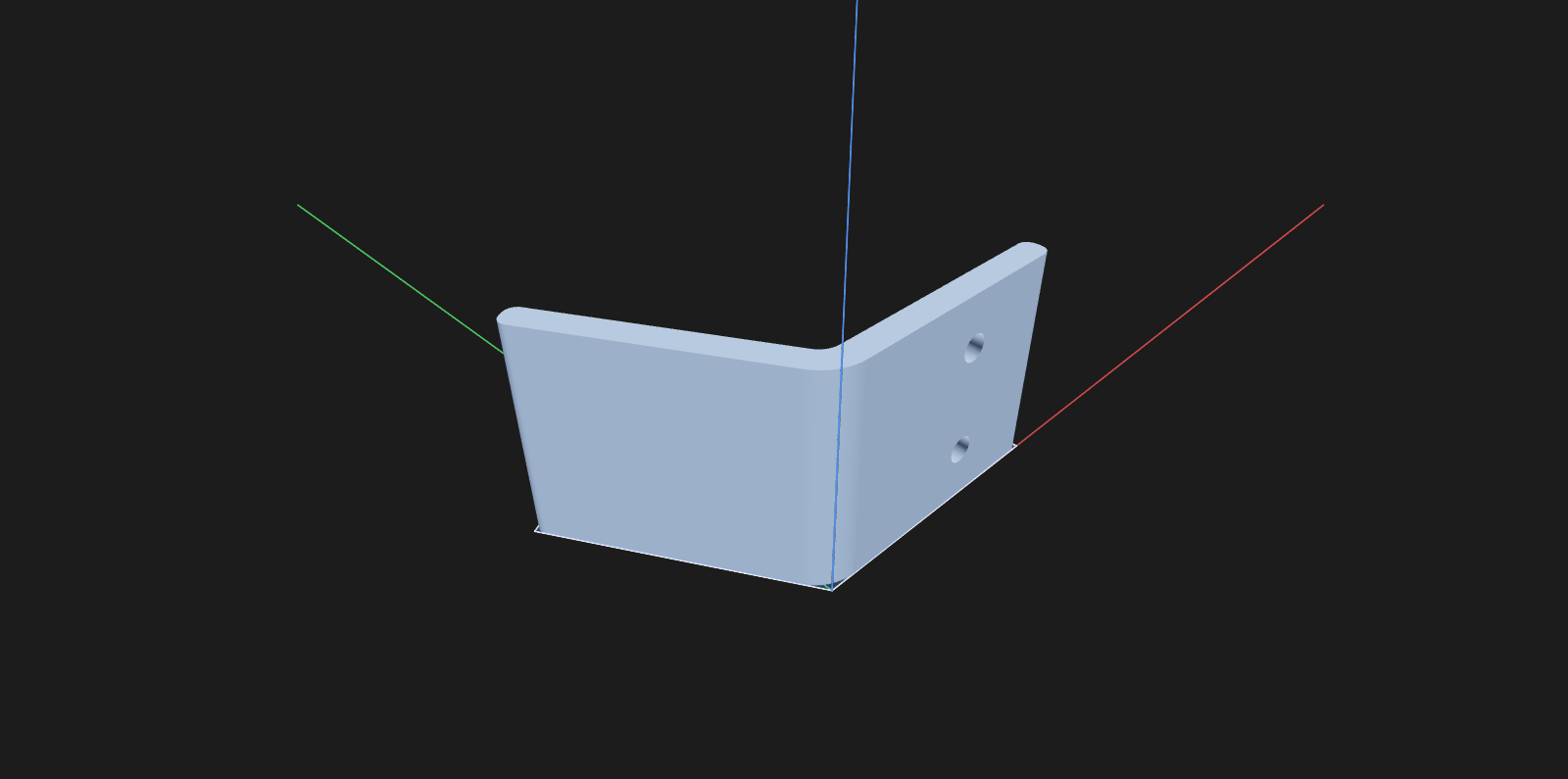
A 120-degree angle bracket: rounded bend, rounded corners, two countersunk screw holes. Draw it sloppily, let the constraint solver square it up, then change the bend angle afterward without redrawing.
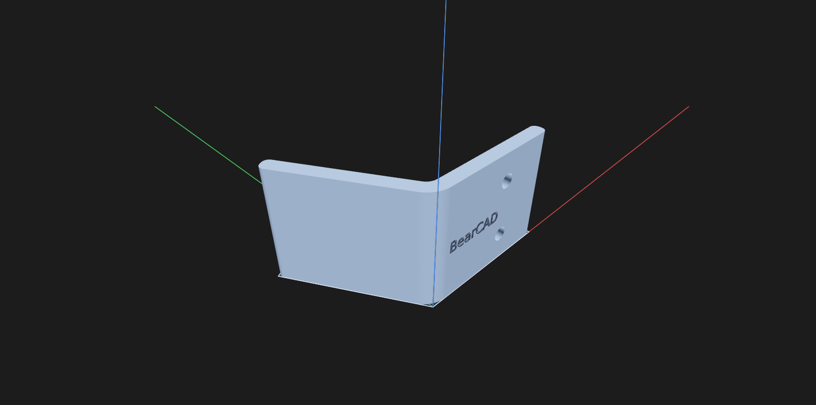
Navigation: right-drag orbits, Shift+right-drag pans, wheel zooms. More in Navigation.
1. Set up parameters
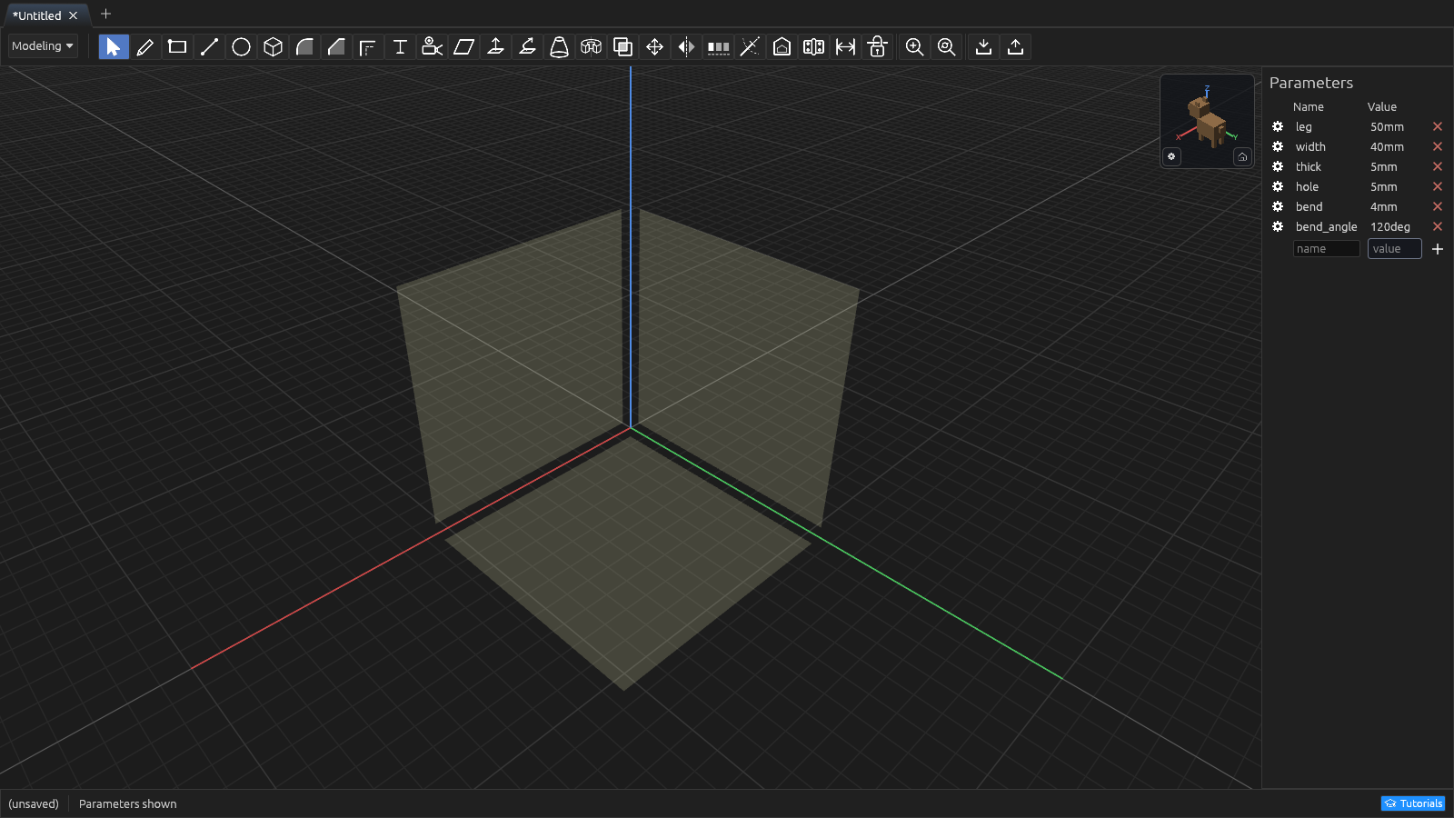
In the Parameters pane, click + and add:
| Name | Value |
|---|---|
leg | 50mm |
width | 40mm |
thick | 5mm |
hole | 5mm |
bend | 4mm |
bend_angle | 120deg |
Any dimension field accepts these names and arithmetic like leg - thick. Typing
name=value in a dimension field creates a parameter on the spot. More in
Parameters & units.
2. Draw the profile — roughly
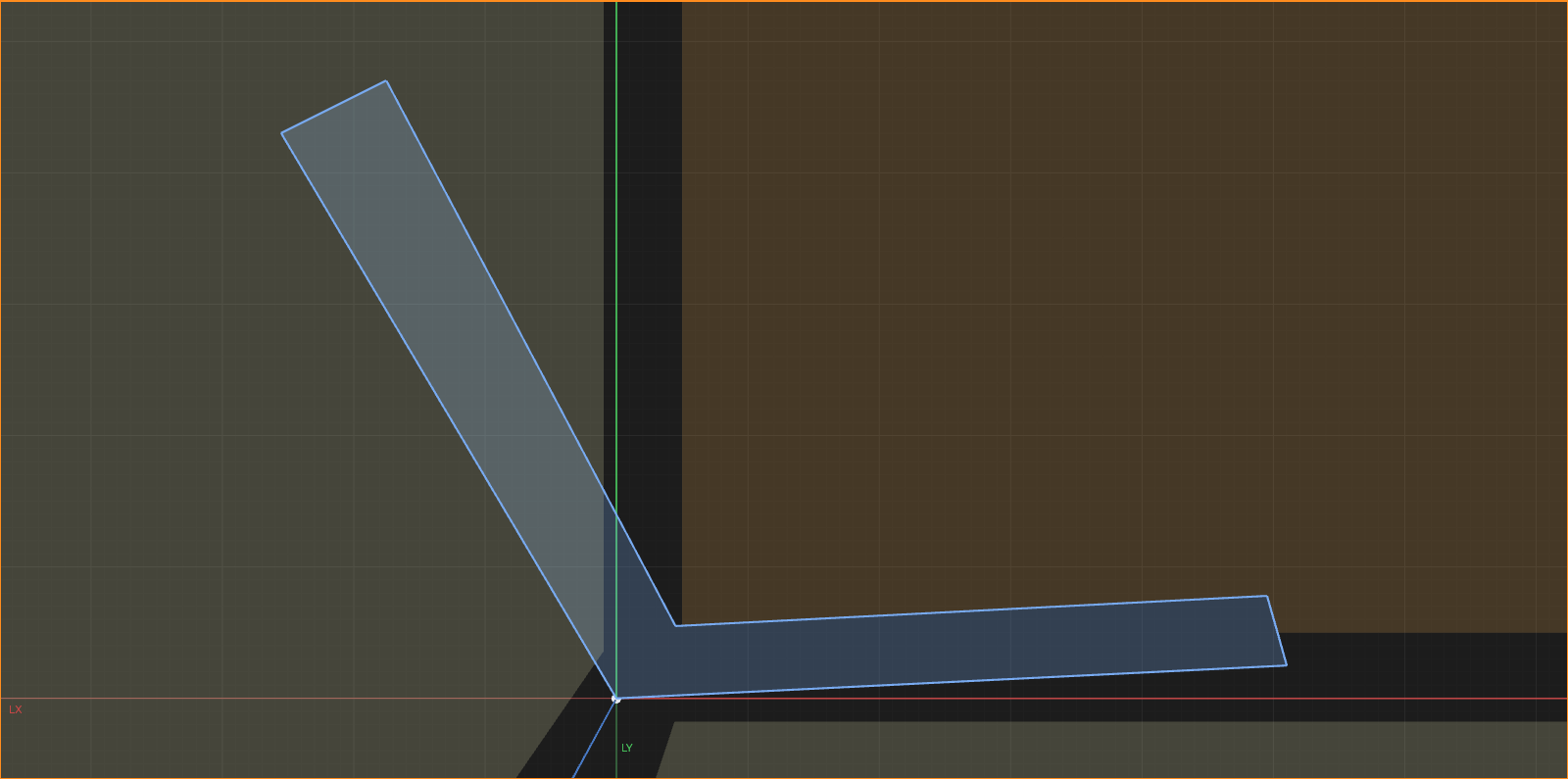
Press L (Line) and click on the ground plane. Clicks chain segments; snapping closes the loop back at the start.
Draw the cross-section as six lines: a long base leg, a short end cap, back along the inside of the base, up the inside of the tilted leg (roughly 120° from the base), a short end cap, and back down to the start. Don't be precise — the next step squares it up. When the loop closes, the profile fills in.
3. Square it up with constraints
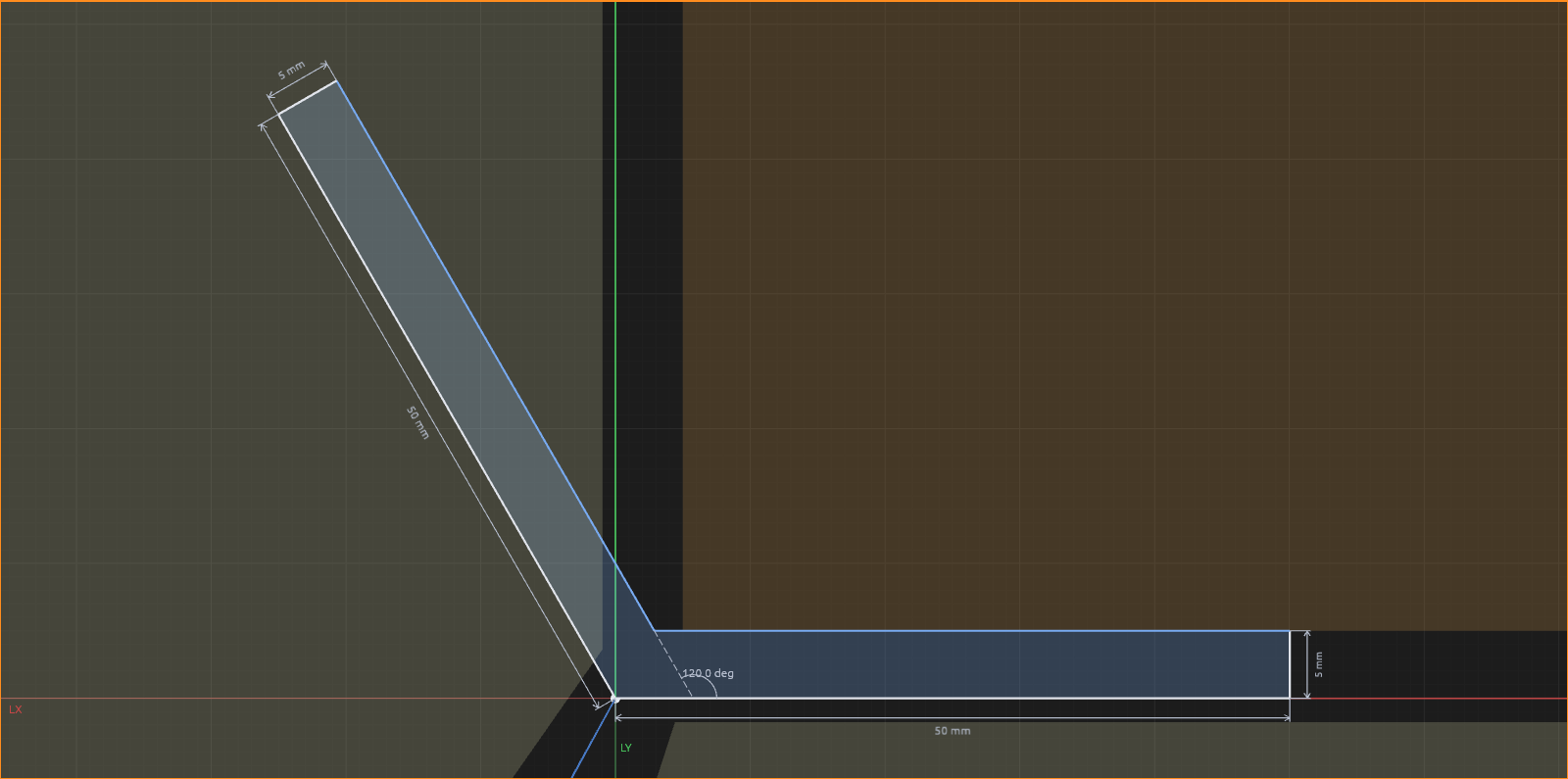
Press C (Constraint). For each constraint, select the line(s), then press its number key:
First pin it down: select the bend corner and the origin, press 4 (Coincident). Then:
- Bottom base line + the X axis: 1 — Parallel (this makes it horizontal).
- Bottom + inner base lines: 1 — Parallel.
- The two tilted leg lines: 1 — Parallel.
- Base end cap + bottom base line: 2 — Perpendicular.
- Leg end cap + outer leg line: 2 — Perpendicular.
Now exact sizes with the Dimension tool (D): click a line, type the value, Enter:
- both outer legs:
leg - both end caps:
thick
For the bend angle: select the bottom base line and the inner leg line, press D,
type bend_angle, Enter.
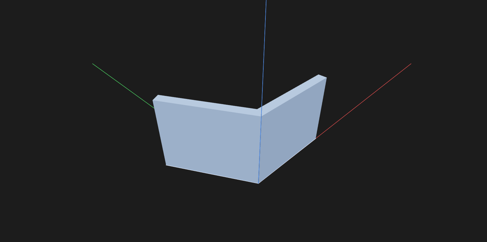
4. Extrude it
Esc to leave the sketch, then E (Extrude). Click the profile face, type width,
Enter.
5. Round the bend
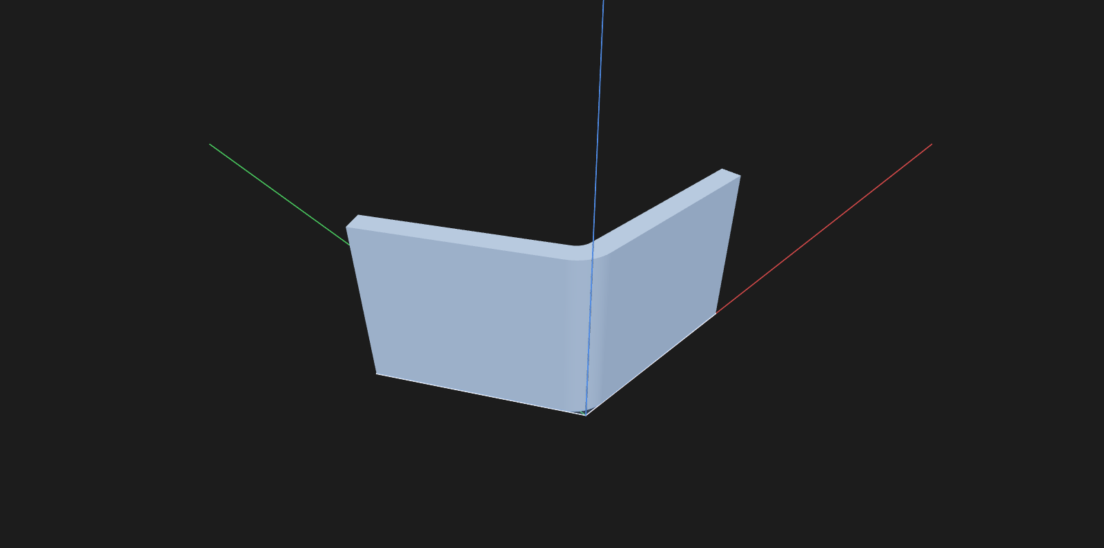
With no sketch open, press F (Fillet):
- Click the inside edge of the bend, type
bend, Enter. - Click the outside edge, type
bend+thick, Enter.
The two rounds are concentric, like bent sheet metal.
6. Cut the screw holes
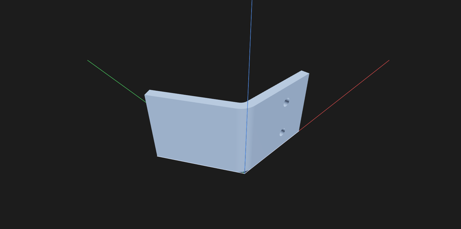
Drill from the inside face of the base flange — where the screw heads sit:
- Press S (Sketch), click the inside face of the base flange.
- Press O (Circle). Click near the flange's tip, type
holefor the diameter, Enter. Place a second circle beside it. - Position them with the Dimension tool (D): click a circle's center and a face edge, type the distance.
- Esc, then E to extrude. Click both circles, drag the handle into the
bracket (or type
thick + 1), pick Cut, Enter.
7. Countersink the holes
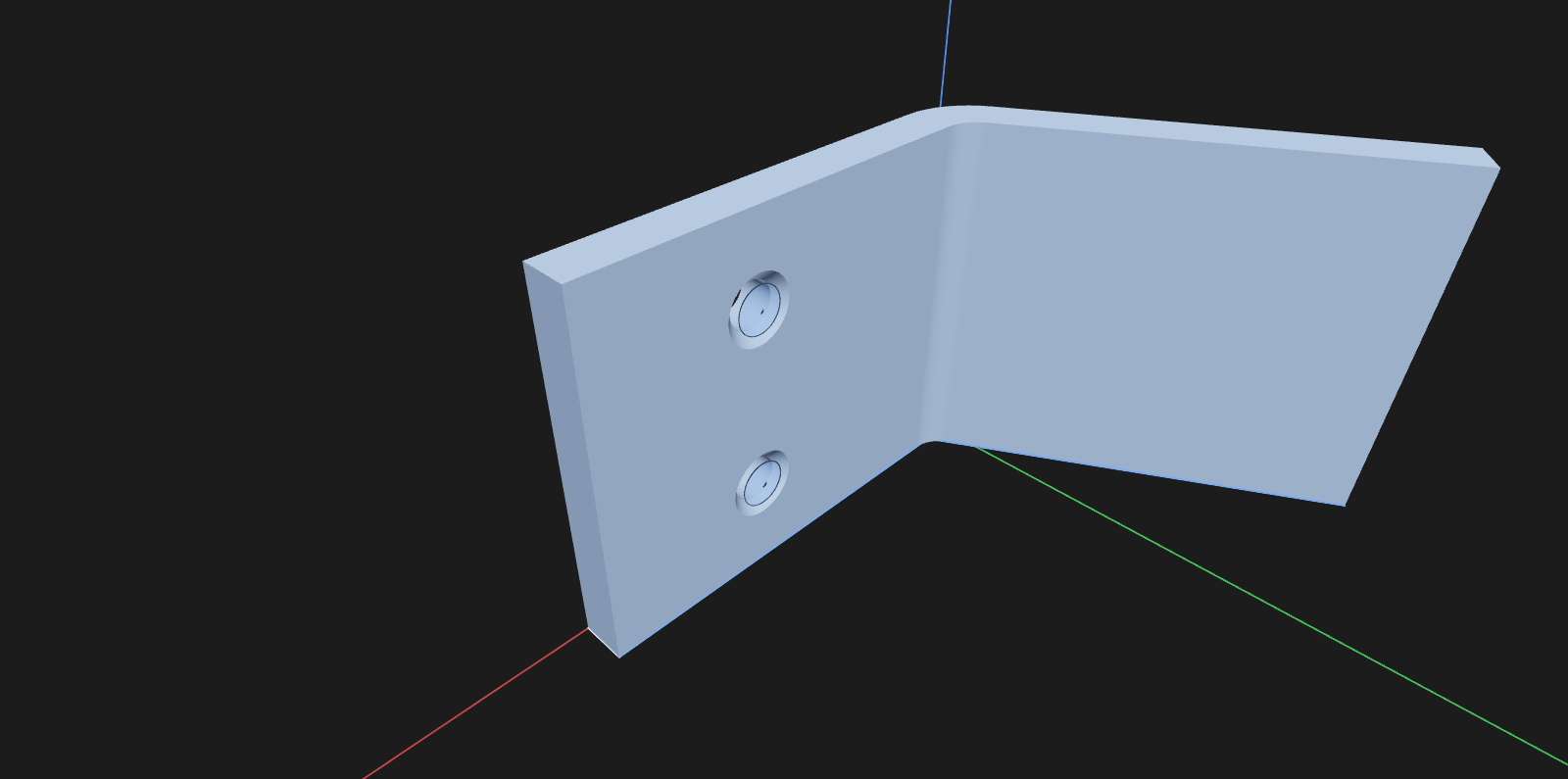
Press K (Chamfer) and click the rim of one hole — where the hole meets the inside
face. Shift+click the other rim, type 1.2, Enter.
8. Round the corners
Press F (Fillet), click a vertical edge at a flange tip, Shift+click the others, type
2, Enter.
9. Engrave a label
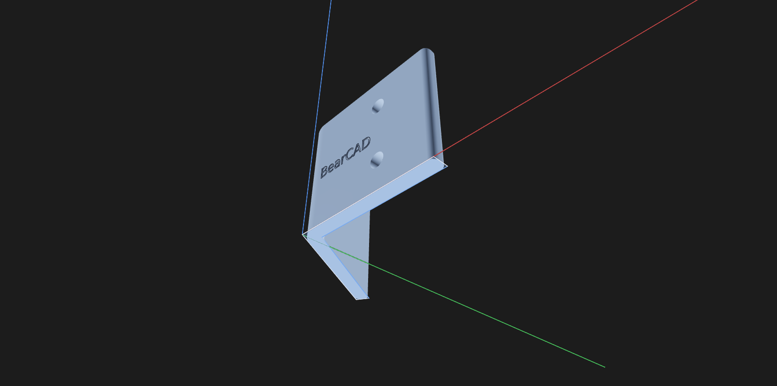
Press T (Text) and click the outer face of the base flange. Type BearCAD and
center it on the face. Press E (Extrude), click the text, push the handle into the
face (type 1), pick Cut — engraved letters.
10. Change your mind
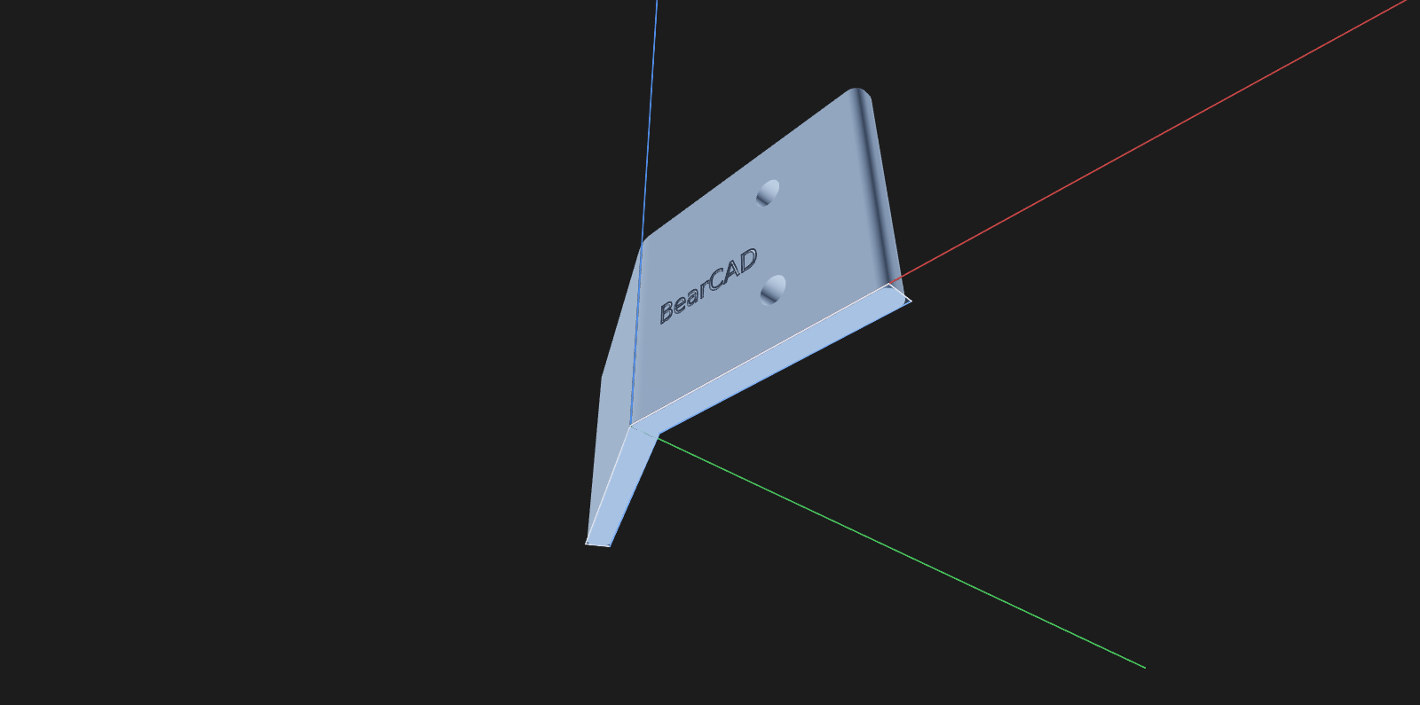
Open the Parameters pane and change bend_angle from 120deg to 150deg. The whole
part rebuilds — bend, holes, countersinks, rounds and all.
11. Export
File → Export → STL… / 3MF… (3D printing) or STEP… (other CAD apps).
Every screenshot on this page is generated automatically from
docs-site/screenshots/quickstart.lua.
If something goes wrong
- Esc cancels what's in progress; again returns to Select.
- Undo (⌘/Ctrl+Z) reverts whole steps.
- The status bar explains what the active tool expects next.
- A red conflict means contradictory constraints — delete the most recent one.