Constraint
Shortcut: C
Constraints state facts about your sketch that BearCAD keeps true: these lines stay parallel, these endpoints stay attached. Where Dimension pins sizes, constraints pin relationships.
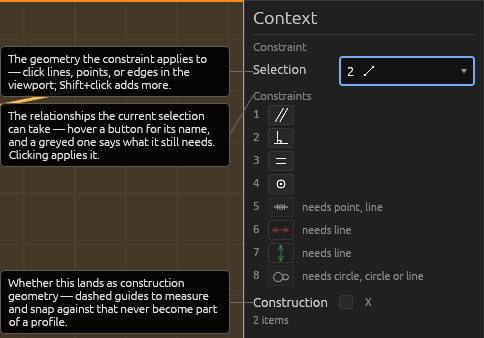
Select the geometry, then click a constraint button or press its number key:
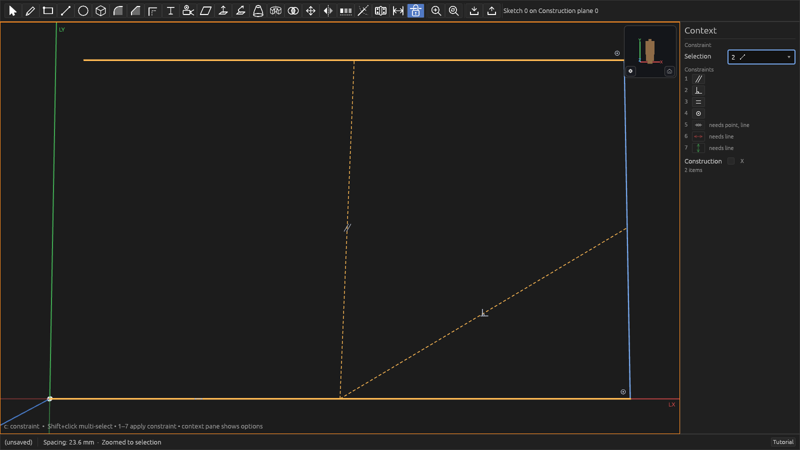
| Constraint | Select first | Key |
|---|---|---|
| Parallel | two lines | 1 |
| Perpendicular | two lines | 2 |
| Equal | two lines | 3 |
| Coincident | two points; a point + a line, circle, or the origin; or two lines (made collinear) | 4 |
| Midpoint | a point + a line | 5 |
| Parallel to X axis | a line | 6 |
| Parallel to Y axis | a line | 7 |
| Tangent | two circles, or a circle + a line | 8 |
Tangent makes rims touch: two circles hug at a single point, or a line grazes a circle. Circles already nested inside one another hug from the inside.
Parallel to X/Y axis are the one-click way to make a line horizontal or vertical — they constrain the selected line parallel to the sketch's X or Y axis. Their buttons draw in the axis's own color — X red, Y green — and the arrow tilts to match the axis's current direction on screen, so the button always shows exactly which way the line will snap. In the viewport, LX and LY labels at the edge mark the local axes in the same colors.
Many constraints also happen automatically while drawing — snapping a line's end onto a point keeps them attached.
When a sketch is drawn on a body's face, the face's own corners and edges can be constrained against too. A tracing image on the sketch's plane offers its corners, edge midpoints, centre, calibration points, and edges the same way.
The origin and its axes
Every sketch shows a floating origin with two axes — X (red) and Y (green) — drawn through the origin so you always know which way the sketch runs. Both are selectable like any other geometry:
- Pin a point to the origin, or hold a point on an axis (which fixes one of its coordinates).
- Select a line and an axis, then press Parallel (
1) or Perpendicular (2), to make the line run along — or square to — that axis. This is how you make a line "horizontal" or "vertical": parallel to the X or Y axis. It works the same on any sketch plane, at any angle, because it refers to the sketch's own axes rather than the screen.
Help