 Move
Move
Shortcut: M
Move slides whole bodies to a new place, producing moved copies.
How to use it
- Pick the Move tool and click one or more bodies. Re-clicking removes one. Pressing M again steps through the Move modes.
- Choose a Move mode:
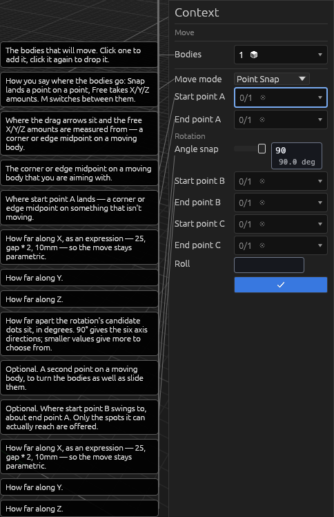
- Point Snap (the default) — pick a Start point A on a moving body, then an End point A on something that isn't moving, and the bodies slide so the first lands on the second. Destination picks ignore the moving bodies, so you can click through them. Either point can be a corner, the midpoint of an edge, or the middle of a flat face; an end point can also be the origin. Hovering marks the exact point a click would take — and while an end picker is armed, the preview glides over to show the move that point would make, before you click. A yellow line connects the two once both are picked. To turn the bodies as well, pick a second pair: Start point B on a moving body and End point B on something that isn't. The bodies then rotate about end point A until start B lands on end B. End point B has to be somewhere start B can actually reach — the same distance from end point A as start B is from start point A — so once you're picking it, every reachable spot is marked: where surrounding edges cross that distance, and mid-air spots straight out along any edge running through end point A, each with a dashed guide line from it. Each spot takes the color of the axis its turn goes about — red for X, green for Y, blue for Z — so spots that turn the same way group together. The one under the cursor turns gold and the preview shows the move you'd get. With both B points picked, a dashed blue curve from start B to end B traces the point's path with the slide and the turn advancing together — half way along, it's half way through both. Lined up on end B, the bodies can still spin about the line from end point A to end point B. A third pair settles that: Start point C on a moving body and End point C wherever it should end up. The bodies spin about that line until start C points at end C, and the placement is then completely decided. End point C can be anywhere — only which way round it sits matters, since how far along and how far out are already set by the other two pairs. Because of that it can only ride a circle, so four spots a quarter turn apart on it are marked in blue: as it sits now, a quarter turn either way, and upside down. Or type a Roll angle instead of picking end point C: the part turns that far about the line from end point A to end point B, which is often quicker than finding a point that says the same thing.
- Face Snap — for Moving face and again for Fixed face, click a face, then click the point on that face that should meet the other. A face offers its corners, the middle of each edge, and its centre — nine points on a rectangular one — and you can reach a corner from just outside the face. Once a face is picked, only points on it are on offer, and what highlights is always what a click takes. The part lands with the one point on the other and the two surfaces together. Flip puts it on the other side instead, and Turn spins it about the fixed face — type a value or drag the yellow ring at the mate point (0° sits on a world axis). A yellow curve leaves each face along its normal and meets the other, and the ghost shows where the part lands.
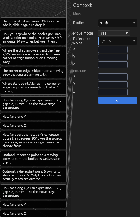
- Free — optionally pick a Reference Point on a moving body, then type the X / Y / Z amounts, or drag the colored arrows on each face of the selection's tight bounding cuboid (all six sides; each axis has a value box beside its +face handle). Under Rotation, type X / Y / Z turns or drag the matching colored rings; they spin the part about its own centre. Everything is an expression, so the move stays parametric.
- Press Enter.
What each pair decides
The same slab landing on the same plate, with one more pair each time.
Each shows the tool mid-pick: the slab still where it started, a ghost where it's going, start A green joined to end A red, and the B and C pairs in blue with the path each point travels.
A alone — start A lands on end A. The slab slides; it faces exactly as it did.
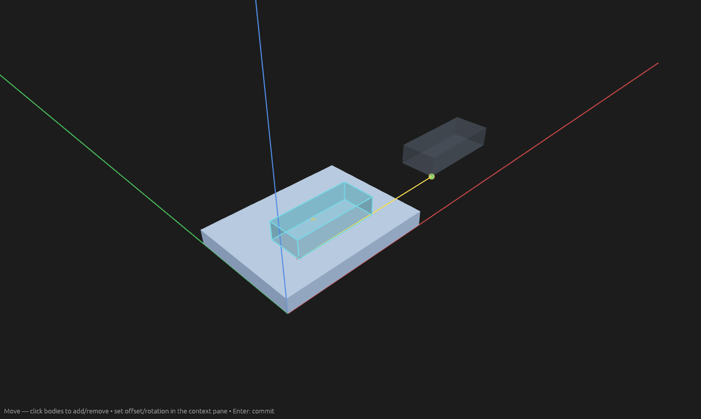
A and B — it also turns about end A until start B points at end B. It can still roll about the line between the two end points.
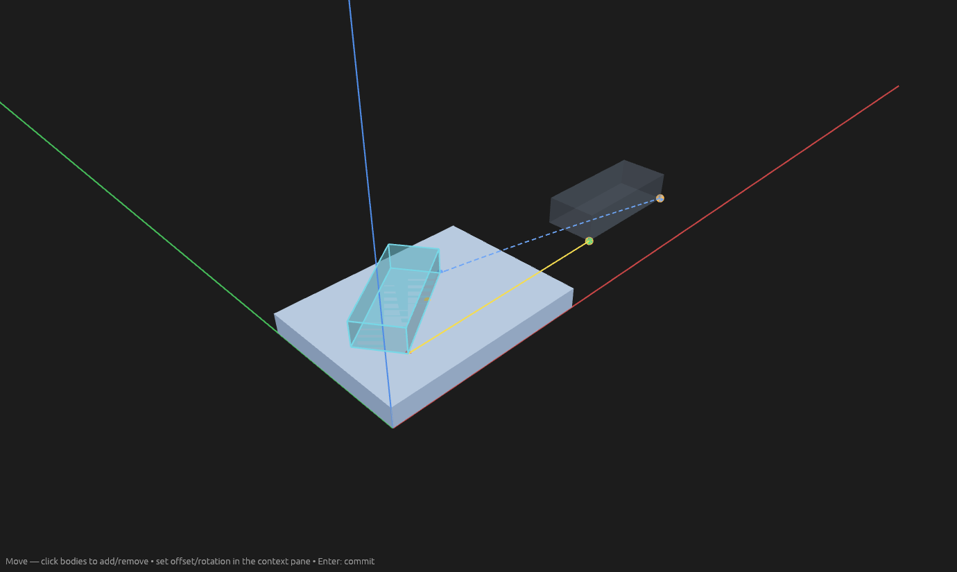
A, B and C — it also spins about that line until start C points at end C, standing it on its long edge. Nothing is left to choose.
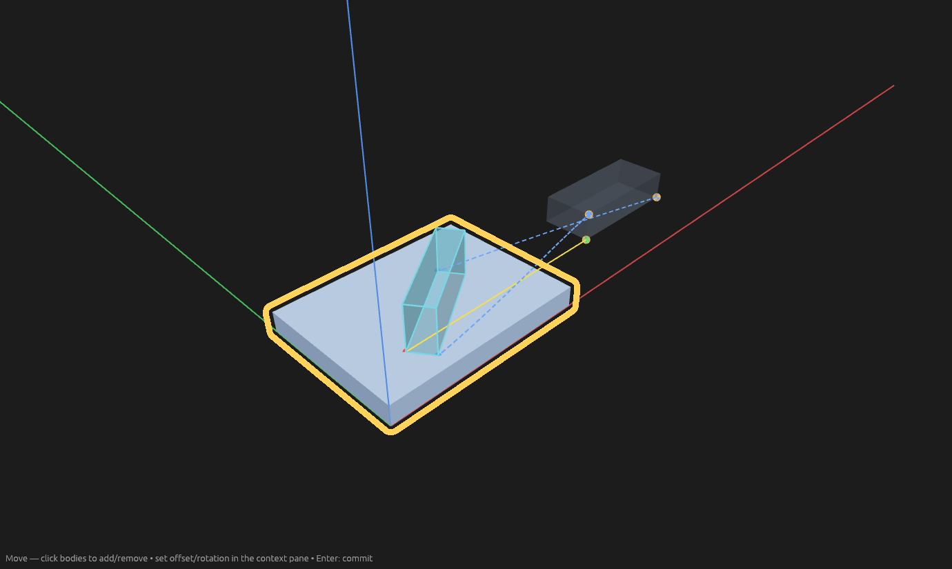
The tool moves you along as you go: pick a body and it's ready for the start point, then the end point, then straight on to Start point B in case you want the turn too, and then to Start point C for the spin. Click any picker to jump back to it. The pane labels the B and C rows Rotation — those four points turn the part, the A pair moves it — and Angle snap at the top of that section sets how far apart the candidate dots sit: 90° offers the six axis directions, 45° offers the diagonals too. Drag the slider or type the angle. Hovering a dot draws the turn that reaches it, in degrees — two arcs for end point B, one for end point C. Under 30° for end point B — 5° for end point C — there are no dots: the sphere (or, for end point C, its circle) is drawn instead and you pick anywhere on it, with the angle reading out as you move.
Help
Moving geometry inside a sketch
Inside a sketch, Move moves sketch geometry. Select lines, circles, or text, then switch to Move: a gizmo appears at the selection's centre. Drag the centre disc to slide freely, or an arrow to move along one axis only.
Constraints keep holding as you drag; a move that would force an edge to stretch is refused (lengths never change).
Moving tracing images
Click a tracing image (or pick it in the Elements pane) with the Move tool. The tool switches to Free. An image never leaves its plane, so only the two in-plane axes slide and only the turn about the plane's normal is offered — the third axis and the two tilting turns are hidden. Face Snap is not a mode for an image; Point Snap is, snapping its nine box points onto other geometry in the plane. The image follows its plane if the plane moves, and the quad previews the slide and turn as you drag. Editing the move back to zero returns it home.
Rotating sketch text
With a single sketch text selected, drag the rotation ring to turn it about its start point.
See Scripting.